Porcelain Insulator News
by Elton Gish, NIA #41
Reprinted from "Crown Jewels of the Wire", August 1991, page 7
DESIGN OF HIGH-VOLTAGE INSULATORS IN 1908
(from lily-shell multiparts to
early suspension types)
Collecting multipart insulators has been very exciting for many collectors
since my book Multipart Porcelain Insulators was published in 1988. Now, over 100 of
you have a copy of the book. Many of you are enjoying the discovery of
"new" specimens abandoned long ago along power lines, substations,
quarries, etc. (not unlike the 1960's for the glass part of our hobby), and the
benefits of trading specimens using the M-numbers. A few of you are keeping a
watchful eye on a scattering of old classic units that have been in service
since before 1910, anxiously waiting for them to come down. After all, a
multipart has never been stolen from an active 40,000-60,000 volt line. In my
book, we discussed briefly the evolution of early multipart insulator design and
how the beautiful lily-shell styles met with early failure.
Here is a little more
information that I found in the February 8, 1908 "Electrical Review".
The article was written by Walter T. Goddard of the Locke Insulator
Manufacturing Co. and read before the Electrical Section of the Canadian Society
of Civil Engineers on December 19, 1907. I will just pull out a few of the
highlights rather than print the entire article, and include other information
as well about early suspension types.
As a general rule [according to Goddard],
two-piece insulators are used for 10,000 to 30,000 volts, three-piece insulators
for 30,000 to 50,000 volts, and four-piece insulators for 66,000 to 70,000
volts. Above 70,000 volts, the underhung or suspension insulator is used with 4-10 shells of
porcelain depending on voltage.
In designing multipart insulators for 1908, the
first consideration was puncture strength. This was a critical error which I
will explain later. Goddard recommended that porcelain shells not be made more
than 5/8" thick. It was not possible at that time to reliably produce
porcelain of greater thickness without internal flaws.
The second design
consideration was to provide as much dry surface as possible under average rain
storm conditions. This was the primary purpose of the lily-shell design. The
upward curving shells would extend the electrical leakage length between the
conductor cable and the pin, and the tall design would allow long, dry areas
between the pin and the inner shell. In some designs, there was almost 12"
of narrow, dry area between the bottom skirt and the pin. The M-3740's found by
Barry Conolly (see April, 1991 CJ) had nearly this entire area next to the pin
filled with Portland cement!
As opposed to straight sides (Fig. 8) where rain
bounces away, the lily-shell design (Fig. 6), bounces rain water upward wetting
the underside of the upper skirts. This action wets nearly the entire leakage
surface of the insulator except for the surface of the inner shell next to the
pin. Consequently, the inner shell is then subjected to almost the entire line
voltage. It is no wonder why insulators such as M-3250, M-3740, and M-3890 were
easily punctured. Remember that voltage is considered a force. During times of
voltage surges from lightning, the electrical current often would find it easier
to pierce one or more of the thin porcelain shells rather than travel the
distance necessary to flash over or arc to the pin.
The single factor contributing to electrical puncture of these early designs
was the height being greater than the diameter. The height of the insulator and
outward flaring skirts provide a very long path for the electrical current to
travel to reach the pin; thus, it inhibited the electrical arcing from crown to
skirt edges to pin. During voltage surges from nearby lightning strikes, it is
easier for the electrical current to force its way through 1, 2, or 3 thin
porcelain shells resulting in electrical puncture. Puncture is the result of an
electrical imbalance across the insulator leaving the inner shell to withstand
nearly the full voltage surge. Puncture is usually evident by a permanent, tiny
hole, and, in severe cases, the puncture hole was through the crown directly to
the top of the pin causing the circuit to short to ground. Punctured insulators
are impossible to detect from the ground, so, in severe cases, each unit had to
be removed and tested. Also, voltage surges, as well as normal heating of the
insulator from current leakage (or puncture), would cause the cement to expand
and break the shells. Lightning arcs, too, could be very damaging to the thin
porcelain skirts, often shattering them.
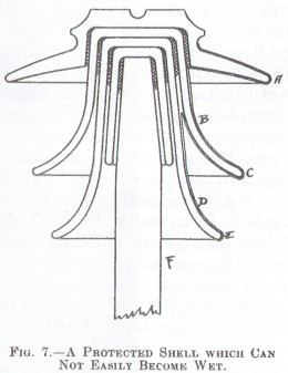
The obvious solution [according to
Goddard] to prevent puncture was to add a fourth recessed shell inside the
insulator as illustrated in Fig. 7. This did reduce the potential for electrical
puncture. However, it added another layer of cement. As the insulator heated up
from the sun and/or electrical leakage and corona effects, the thick layers of
cement would expand laterally and crack the shells. In some cases, the shells
would crack so severely that they would break apart. By 1908, this was already
becoming a major problem with three-part lily-shell designs such as M-3250,
M-3740, and most notably with M-3890.
M-3890's damaged by lightning in 1908
The massive failure of M-3890's on the 160-mile, 60,000 volt Niagara,
Lockport and Ontario line from 1906-1908 due to lightning strikes (see the
photograph above) brought about a new realization of how to design multipart
insulators. When 11,000 insulators were removed and tested, it was found that
40% of them had puncture damage of one or more shells. 82% of the puncture
failures involved the inner shell with almost 56% of the failures involving just
the inner shell. It was quite obvious that the inner shell was receiving the
majority of the electrical stress from voltage surges. The M-3890' s that
passed the test were placed on the bottom crossarm. The single, top insulator,
which position received the most damage from lightning, was replaced with M-4338
early in 1909.
M-4338 was specifically designed, in the light of experience on
this line, to be six inches shorter. They found that long, thin insulator parts,
as in M-3890, could not resist mechanical shock of lightning. Moreover, they
discovered that short shells would allow a more even distribution of voltage
across the entire body of the insulator; therefore, reducing the electrical
stress on the inner shell, and reducing the chance of puncture. The shells were
made thicker, too, to resist breaking, and a fourth, recessed inner shell was
added for additional protection against puncture; however, it probably was not
needed. In short, the new four-part insulator was designed to flash over rather
than to puncture. This was the first realization of the benefit to an insulator
design with a diameter to height ratio of less than 1: 1.
The new designs incorporating the fourth, recessed inner shell and the
diameter to height ratio of less than 1: 1 are M-4325C, M-4332, M-4338, M-4339,
M-4415, M-4415A, M-4600, M-4605, M-4606, M-4608, and M-4800. We do know that
M-4325C, M-4415, M-4415A made by Thomas and M-4600 made by Lima were
probably made before 1908 (a few of these are still in use in California). These
three styles are similar in that they all have ridges under the top skirt (more
on that feature in a future PIN article). I find it puzzling that M-4338 was
developed in 1908 on the east coast to meet a specific need, but other insulator
companies, too, picked up on the design change to supply insulators to the west
coast.
It should be noted that M-4338 is not the grey Ohio Brass crosstop
(without recessed fourth shell) that several people have in their collection (It
was assigned M-4395). Specimens of M-4338 have not been found.
The benefits of
the new, shorter designs were slow to become widely excepted. Along with many
lily-shell styles shown in the 1917 Parker catalog which still exhibited long,
thin shells, there was the outdated M-4390. This insulator still had a height to
diameter ratio that was greater than 1. The use of the recessed fourth skirt
persisted as late as 1939 with the Westinghouse M-4340. This was probably still
a good idea since the cement expansion problem had been overcome in the 1920's.
M-3890
L. C. Nicholson, the electrical engineer working on the Niagara, Lockport and
Ontario line, sought to remedy the problem of severely damaging lightning arcs
on M-3890 by installing an arcing ring around the bottom of the insulator. This
provided some relief by allowing voltage surges to arc around the insulator to
the arcing ring, thus protecting the thin skirts from both breakage by the arc and from electrical puncture. The
rings also reduced the burning damage caused by the arc on the surface of the
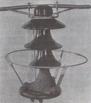
insulator. The photo on the previous page shows M-3890 with a "Nicholson
arcing ring". It probably was an expensive fix. Even when damaged units
were replaced with M-4338, they were also fitted with Nicholson arcing rings
(photo below). So, you can see that they still did not yet fully comprehend what
was happening. With massive failures of M-3890, it was time for drastic action
with little time for experimentation to better understand the problem. The rings
would later be called "grading rings" and were used to equalize or
grade the voltage over the suspension string.
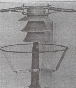
M-4338 fitted with Nicholson arcing rings in 1909
Nicholson obtained three patents
covering the arcing ring design. Two were for multipart insulators and one for
suspension insulators.
Goddard stated that the straight sided shells on the insulator shown in Fig.
8 would probably stay dry longer during a rain, but that the lily-shell design
would provide a greater leakage path and offer greater electrical resistance. We
now know that the leakage path should not be the entire consideration.
In an
article in "Electrical World" dated December 22, 1909 titled
"Present Status of European Practice in Transmission Line Work", it
was believed in Switzerland that rounded skirt edges would cause the rain water
to run under and drop on the surface of the lower skirts.
They favored a
slightly upward curved skirt edge that would allow the water to drop off to a
sharp point missing the skirt below. This idea may have some merit if it were
not for the other problems with lily-shell styles. The Swiss attempted to solve
the cement problem by using a mixture of sulfur and plaster which was made
non-porous by coating it with shellac.
Other Swiss experts had good results with screwing two or more shells
together and then re-firing to fuse the pieces into a single unit. At least one
35,000 volt line in Germany utilized insulators made in one piece to eliminate
the problems with cementing!
Pin type insulators have a practical limitation.
Insulators with more than four shells were never shown to be practical. The only
reference that I have found about a five-part insulator was in Brent Mills'
book, Porcelain Insulators and How They Grew. It was rated at a working voltage
of 120,000 volts and shown in the 1920 Pittsburg catalog! I wish I could find a
copy of that catalog. Knowing Pittsburg's penchant for cataloging a multitude of
odd, difficult to make styles, I seriously doubt that they ever made a five-part
insulator [Pittsburg also cataloged a porcelain CD 147 in their catalog No.2
circa 1918!].
Adding additional shells compounded the cement expansion problem
as well as making the insulators much too heavy to handle and mount on a tower.
What would they have used as a pin for a five-part multi?! M-3490 already used a
wooden pin that was almost as big as a baseball bat [Bill Rohde retrieved
several of these heavy pins]. Therefore, the suspension insulator was the next
logical step for transmission of voltages greater than 60,000 volts. They
offered the advantage of size, cheapness of manufacture, and, most notable, by
simply adding additional units to the string, you could easily increase line
voltage. Suspension insulators allowed transmission of power at 70,000 to
1,000,000 volts, far surpassing the pin type practical limitation of 70,000
volts. Below 70,000 volts, pin types were cheaper. Also, if one of the
suspension units was damaged, it would only slightly reduce the effectiveness of
the entire string. It could be easily replaced at leisure without experiencing
severe or total line failure. However, early suspension designs were rooted in
thinking about problems with pin type insulators; namely, puncture resistance.
Goddard and others believed that one should first design the suspension
insulator against puncture and then leakage distance.
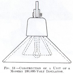
To this end, Fig 13, with
its' two-part suspension design, was the recommendation. Again, cementing of the
two porcelain shells was a major problem. The cement expansion would soon crack the porcelain shells and result in
insulator failure or worse, dropping of the conductor! These suspension
units were made up to 14" in diameter! They were quite heavy and
problems were experienced with both cement expansion, and cemented metal pins
and hooks, pulling out of the cement. The mechanical strength of these early units
became inferior after a short time in operation.
These early two-piece suspension insulators must now be
very scarce. Ben Kirsten has found a specimen of a Thomas 14"
two-piece suspension unit (see Ben's drawing on the next page). He says that it
has a red-brown glaze color, and it weighs
23 pounds! A string of 6 of these units would weigh 138 pounds! A string of 6
modern 10" suspension disks would only weigh 63 pounds.
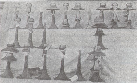
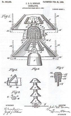
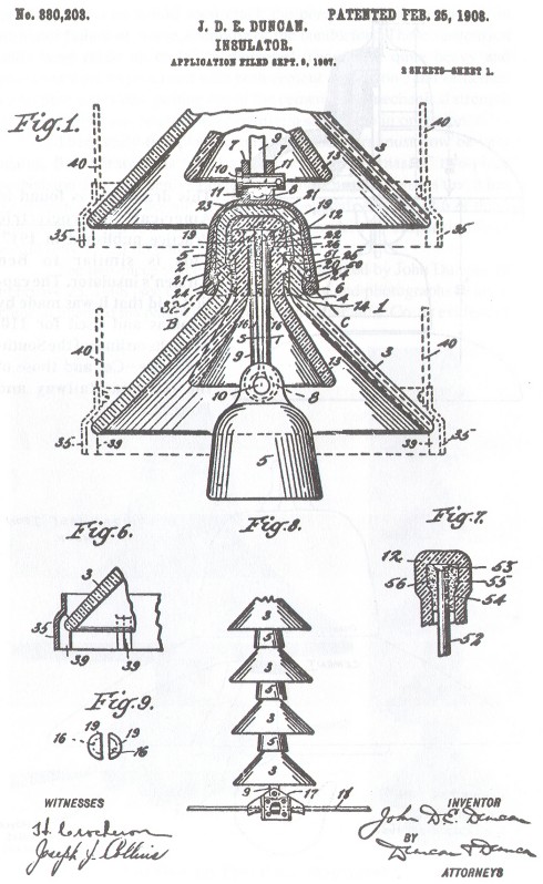
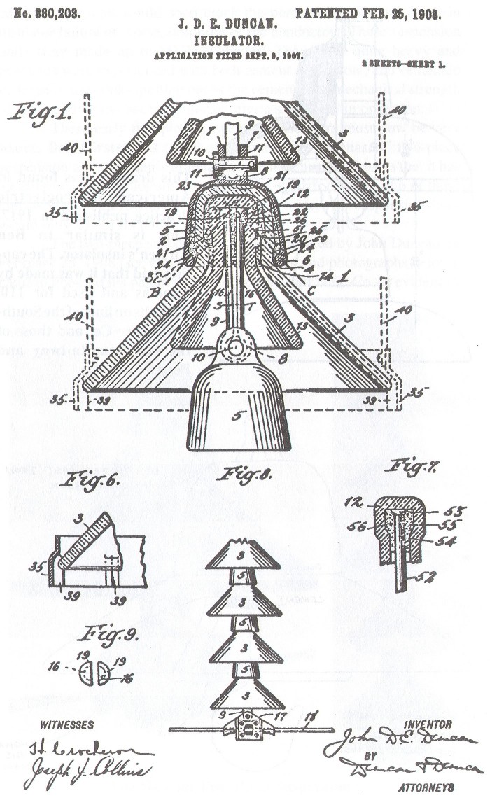
The two-piece suspension unit was patented by John Duncan on
February 25, 1908 (see copy of patent drawing and photographs below). Duncan
licensed his patent to the Locke Insulator Mfg. Co. as evidenced by the above two photographs taken from the
Journal of Electricity, Power and
Gas dated October 5, 1907, less than one month after the patent application was
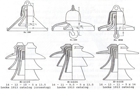
filed. Three sizes of the two-piece suspension units were shown in the 1913
Locke catalog (see end of this article) and two sizes in the 1916 Locke catalog.
A 1920 Thomas catalog is the earliest one that I have, and no two-piece
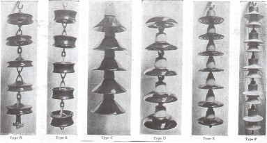
suspensions were shown. Also included at the end of this article is a photograph
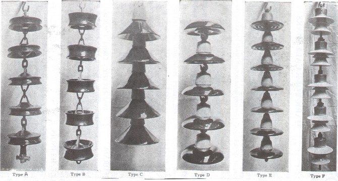
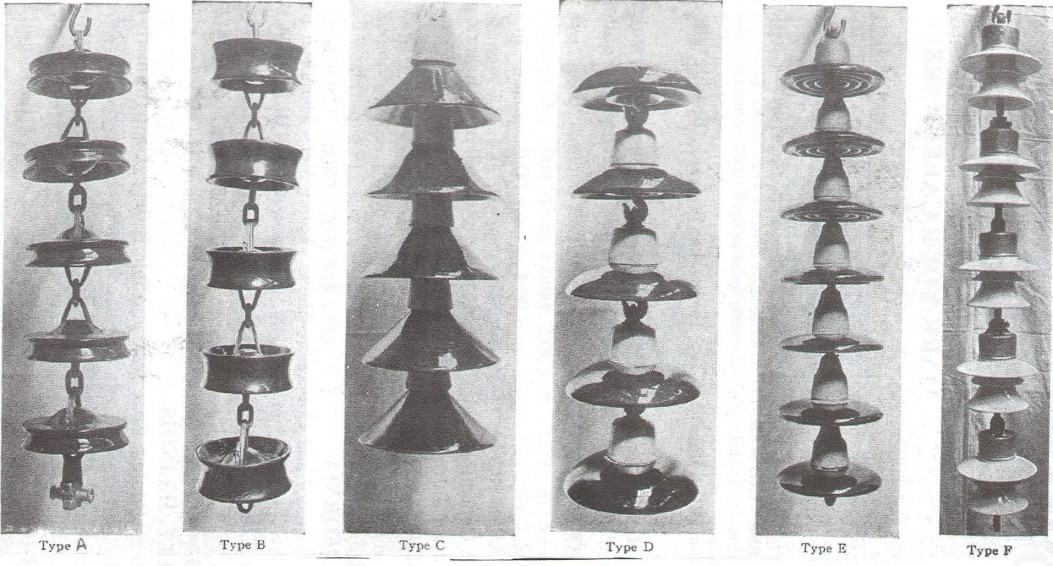
of several types of suspension insulators which appeared in the AIEE journal
dated December 13, 1912 as part of an article by P. W. Sothman on testing
suspension insulators. Suspension disks similar to Ben Kirsten's Thomas
insulator is "Type D" in the photograph. Sothman's conclusions on
testing "Type D" were:
"This type meets electrical and mechanical tests. Insulator has,
however, very faulty design. Diameter too large; weight and bulk too high.
Inefficient cementing of hook. Hook failure to be condemned, causing distortion
of [electrical] field and premature discharge. As a two-piece insulator,
electrical stresses of petticoats are not balanced."
The hook in those tests would pull out due to cement failure under the load
of the conductor, but the unit was stronger than most of the other suspension
types tested. The two-piece style was not very practical because the metal cap
had to be larger to accommodate the extra thickness of two shells; thus, it was
heavier and bulkier.
In 1908, Goddard and others correctly believed that an
insulator should not be regarded as a barrier to current, but rather as a
high-resistance path between the line and earth. By providing an insulator with
additional shells and using lily-shell skirts, they believed that the
high-resistance (and puncture) requirement was met.
The electrical fields of
high voltage transmission lines and their effects on insulators did not reach an
adequate level of understanding until the late 1910' s. Up until this time, many
engineers involved in high voltage insulator design were wandering aimlessly.
Designs reflected the whims and wants of each purchasing agent or power company
specifications (again reference the multipart styles shown in the 1917 Parker
catalog in Brent Mills book). It was the Faradoid patent (1,374,998) granted to
Fortescue and Gilchrist on April 19 , 1921 that educated the insulator industry
to what was really causing insulator failures, and what could be done to provide
a genuine improvement in multipart design.
The development of the suspension
disk insulator was delayed many years until reliable cementing techniques could be developed for the cap
and pin assembly. During this development period, the power transmission
industry was forced to rely on the inferior Hewlett suspension disk. The
Hewletts were manufactured originally by General Electric (holders of the
patent). Later, due to demand out-stripping General Electric's production, the
manufacture of the Hewlett was licensed to Locke and Thomas. This story will
have to wait until another time.
These suspension styles are from the 1913 Locke
catalog. Multipart styles (below) are "new" M-numbers that are not
shown in my book, Multipart Porcelain Insulators, but are referenced in this
article.
Medium Image (79 Kb)
Large Image (207 Kb)
[From AlEE Journal dated December 13, 1912]
"Type D" is the
Duncan two-piece suspension insulator of a more modern curved style. "Type
A" is the Hewlett. "Type B" is the new "fishtail"
Hewlett for strain service. "Type C" is an early one-piece suspension.
"Type E" is a modern style of suspension disk with petticoats.
"Type F" is of foreign manufacture which used plaster rather than
Portland cement. to attach the metal pin and cap. This unit did not test well
because of the poor holding power of the plaster.
Medium Image (109 Kb)
Large Image (214 Kb)
|

)
)
)
)
)
)
)
)
)
)
)
)
)
)